
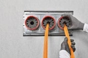
Cables going through a firestop penetration can pose challenges
Opening size, cable type, sleeves, wall or floor type, and hourly fire rating can all influence the capabilities of a firestop material to function properly. Some electrical cable applications have specific requirements that can greatly assist in selecting the correct firestop product and system. One very important parameter is the ‘cable load’ or ‘cable fill’. Understanding this concept, how to calculate it and knowing the capabilities of different firestop products can help ensure you select the proper system for your application.
Why is there a percent fill limitation for cables?
In a hospital, you can easily find more than 300-400 km of power, communication and security system cables. Similar situations are common in other building types such as hotels, airports and industrial facilities or commercial structures like shopping malls. This poses a big task for electrical planners to correctly plan and specify the electrical infrastructure of a building. Often, cables need go through fire-rated walls and floors, which, again poses new challenges. When cables, cable bundles or cables on a tray are routed through fire-rated walls and floors, these penetrations have to be restored to maintain the hourly ratings of the building element. This is typically done with firestopping systems containing firestopping materials, such as caulk, preformed devices, etc. During fire conditions, cables begin to melt and burn away allowing the metal conductors to collapse together. This reduces the overall diameter of a cable bundle thereby allowing more space for flames and smoke to travel through. When this occurs, there must be a sufficient amount of firestop material to maintain the integrity of firestopping system. For this reason, intumescent firestopping products are generally preferred for cable penetrations. During fire conditions, these materials are designed to expand and compress any voids that may be created in a fire-rated partition.
The general cable fill rule and the reasoning behind it
Classic cable penetrations generally have to be installed according to the 60% rule. This is stated in fire test standards, such as EN1366-3 in Europe. This rule means the maximum fill ratio of the area with cables and other components through an opening should not exceed 60%. The remaining 40% must be filled with “active” firestop material. In other words, there must be enough firestop material in the opening to be capable of filling the gaps, holes and leakages created when cables burn and melt in a fire. This in addition to also achieving a decent smoke seal can become a challenge.
So, what are factors that influence cable load? The answer isn’t always clear. Cable load can be limited by the type and size of cables, construction type, sleeved or unsleeved openings and the capabilities of the firestop material being utilized. The installation method of the firestop itself can also be a limiting factor. Putties and blocks are packed around openings where sealants or firestop foams can be installed between and around cables. Knowing the tested and approved cable fill of an opening and remaining within the guidelines of a UL listing or of an approval like an ETA (European Technical Assessment) is important to properly firestop a cable penetration.
How to calculate cable load or cable fill
The measurement method for this calculation is the “percent fill”. This is typically referred to as the cross-sectional area of an opening that is occupied by penetrating items. This term frequently appears in the respective approvals or the listing of the product. Below is an example of the calculation of percent fill within a cable penetration with more than one cable type.
Exercise: Calculating percent fill with multiple cable types. Calculated percent fill for this opening (approx. numbers due to rounding)
· Diameter of opening = 4 in (approx.100mm)
· 7 cables with diameter ½ in (approx. 1.3cm)
· 6 cables with diameter ¾ in (approx. 1,9cm)
· Area of opening Ao = π x or 3.14 x 2 = 12.56 in2 (approx. 78,5cm2)
· Area of one ½” cable c1 = π x r2 or 3.14 x .0.2502 = 0.196 in2 (approx. 1,33cm2)
· Area of one ¾” cable c2 = π x r2 or 3.14 x 0.3752 = 0.442 in2 (approx. 2,83cm2)
· Percent Fill = ((Ac1 x N1) (Ac2 x N2) / (Ao)) x 100 = ((0.196 x 7) (0.442 x 6) / 12.56) x 100 =
Approx. 32-33%!
Important for all electrical planners
There are basically four conventions for professional and application-oriented early planning and design in the electrical trade. This is because the optimal size and arrangement of fire-rated penetrations in walls or floors are designed to help safeguard both people and assets.
1. Professional: selection of approved firestop systems
2. Application and use oriented: clear split of the penetrations and cable ways concerning application and end usage (power, communication, etc.), which also enable easier repenetration and organization/documentation. Preferably, different openings for electrical and mechanical (heating, ventilation, water supply) applications should be considered.
3. Early: a clear consideration of cable penetrations and solution-oriented selections in the pre-planning phase to better avoid problems, deficiencies and expensive rework in later phases. Clear specification of solutions and products.
4. Documentation: detailed check and inspection of installation quality with professional documentation that includes pictures and locations.
With these four conventions, planners and designers can better avoid major problems in projects like datacenters, hospitals with high cable traffic or when retrofitting during the operation phase of a building or facility.
Smart and flexible firestop solutions
Hilti offers the CFS-SL GA Speed Sleeve which is ideal for sealing penetrations for cable bundles and is suitable for small to medium-sized openings in walls and ceilings!
Other features include:
- Functional and compliant when properly installed
- Twist-to-close mechanism – for easier and remote re-penetration while protecting cables
- Straightforward inspection – you can see if the sleeve is closed without having to check behind a covering fringe above the ceiling
- Superior smoke tightness and airflow control thanks to its twisting mechanism
- Smoke gaskets eliminate need for sealant or putty
The CFS-SL GA Speed Sleeve is the most ideal solution for you!